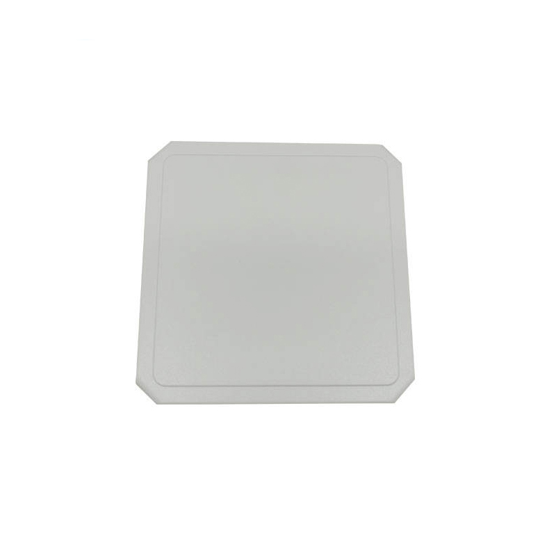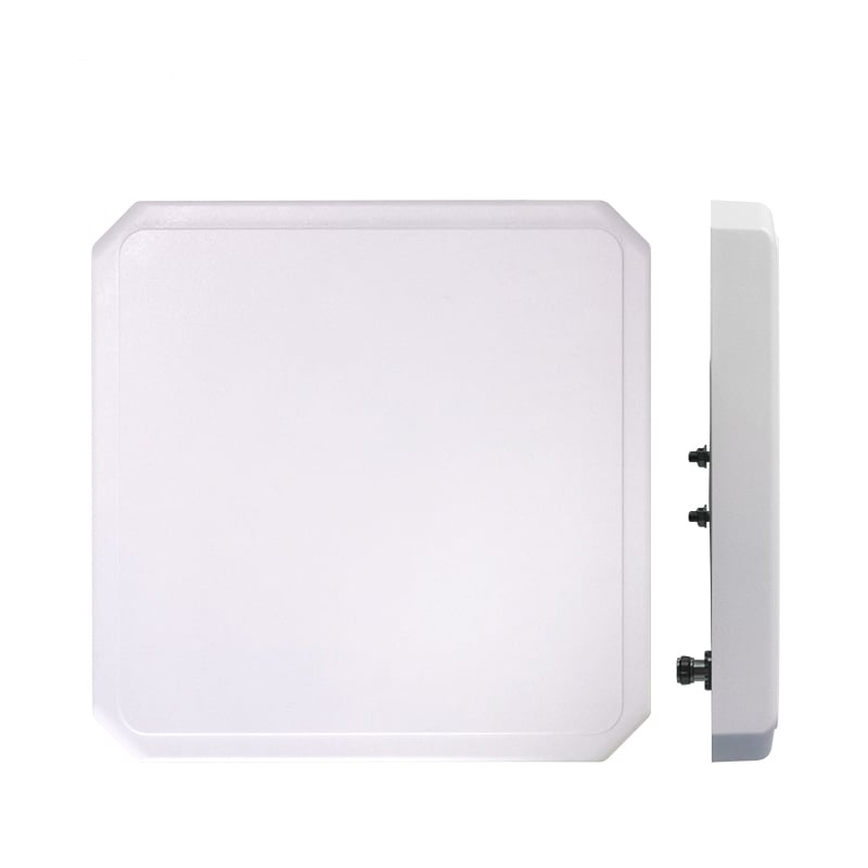

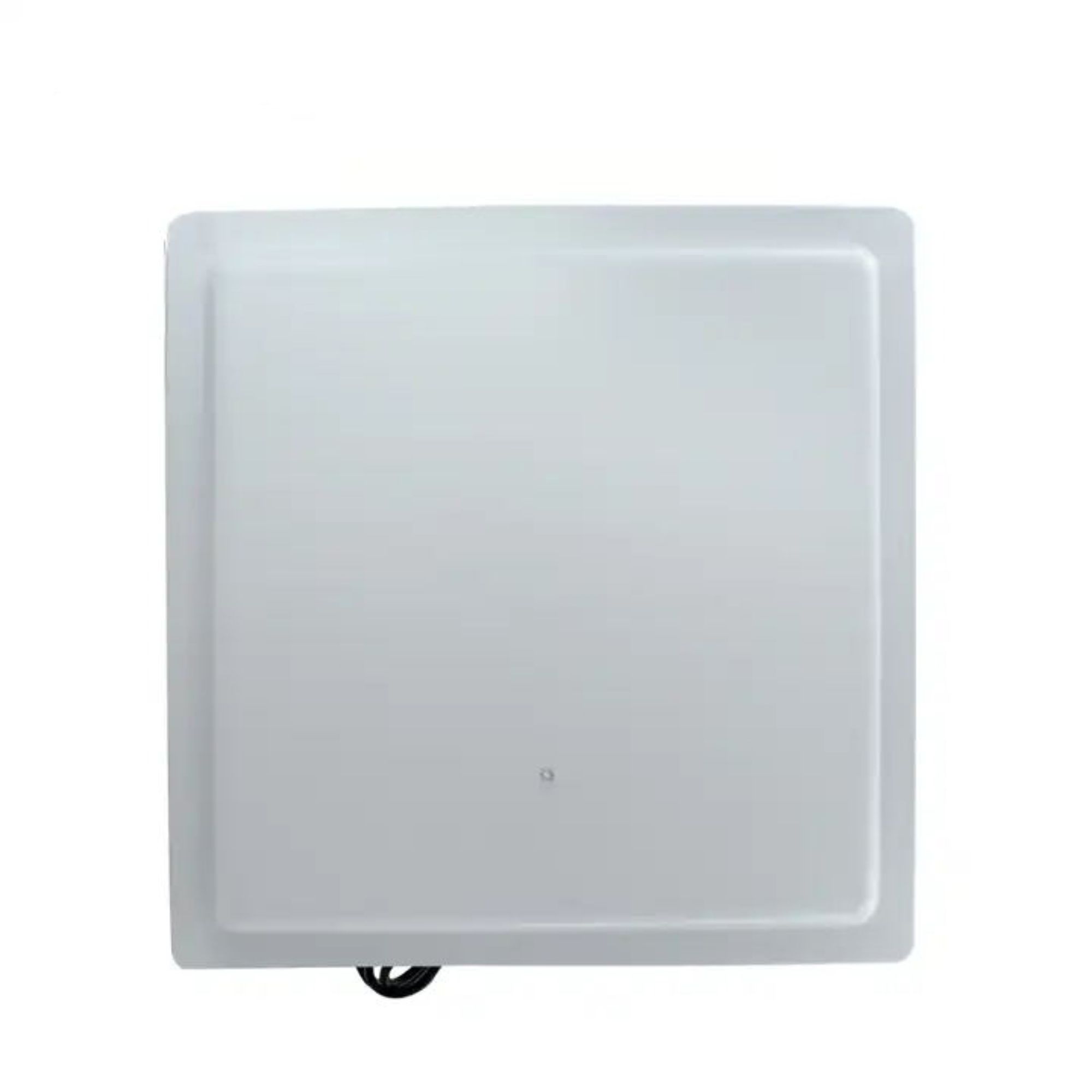
Twelve dBi of gain, 42 by 38 degree beam, linear polarisation, VSWR at or below 1.3. Sealed to IP65, rated to 30 m/s of wind, DC grounded to the mounting plate. It is a piece of metal and plastic — everything it does comes from the reader you connect to it.
What 12 dBi covers
Twelve dBi buys reach by making the beam narrow. The number a site plan actually needs is the size of the patch on the floor at the distance that matters — and that falls straight out of the two beamwidths above.
At any distance d from the panel, coverage is 0.77 × d wide and 0.69 × d tall.
The same cone in the vertical plane gives 0.69 × d, so the patch is slightly wider than it is tall.
| DISTANCE | COVERAGE WIDTH | COVERAGE HEIGHT | TYPICAL USE |
| 3 m | 2.3 m | 2.1 m | One dock door, one conveyor lane |
| 5 m | 3.8 m | 3.4 m | A vehicle lane, a pair of gates |
| 10 m | 7.7 m | 6.9 m | A yard entrance, an aisle mouth |
| 15 m | 11.5 m | 10.3 m | The far edge of a long-throw install |
The decision that decides whether a site works
This antenna is linearly polarised. For a fixed reader that one word sets the site survey, the mounting angle, and whether the tags answer at all.
Every passive UHF tag carries a linear dipole. Aligned with the antenna, they couple fully. Rotated 45 degrees, half the power is lost — exactly 3 dB, which cuts range by about 30 per cent. Rotated 90 degrees, the two are cross-polarised and the tag stops answering, no matter how much power you push into it.
The loss is geometric, not a tuning problem. It is why a linear panel suits a conveyor of identically oriented cartons and fails on a doorway of people.
Cartons on a conveyor, pallets on a fixed path, vehicle windscreen labels, a gate where the tag is always vertical. A linear panel puts all of its gain into one plane, so it reaches roughly 3 dB further than a circular antenna of the same size — which is a long way in metres.
People walking through a portal, garments on a rail, loose assets in a bin, anything a human carries. A circular antenna reads at any rotation and pays for it with about 3 dB, which you recover with a shorter throw or a second port. This panel is linear only — if your tags arrive at random angles, tell us and we will point you at the right antenna instead of selling you this one.
Specification
Grouped the way an installer reads it: radio first, then the mechanical interface you need before you can mount it.
| PARAMETER | VALUE |
| RADIO | |
| Frequency range | 902–928 MHz. For ETSI markets, ask us about the 865–868 MHz version — it is a different antenna and needs its own measured VSWR curve. |
| Gain | 12 dBi |
| Horizontal beamwidth | 42° |
| Vertical beamwidth | 38° |
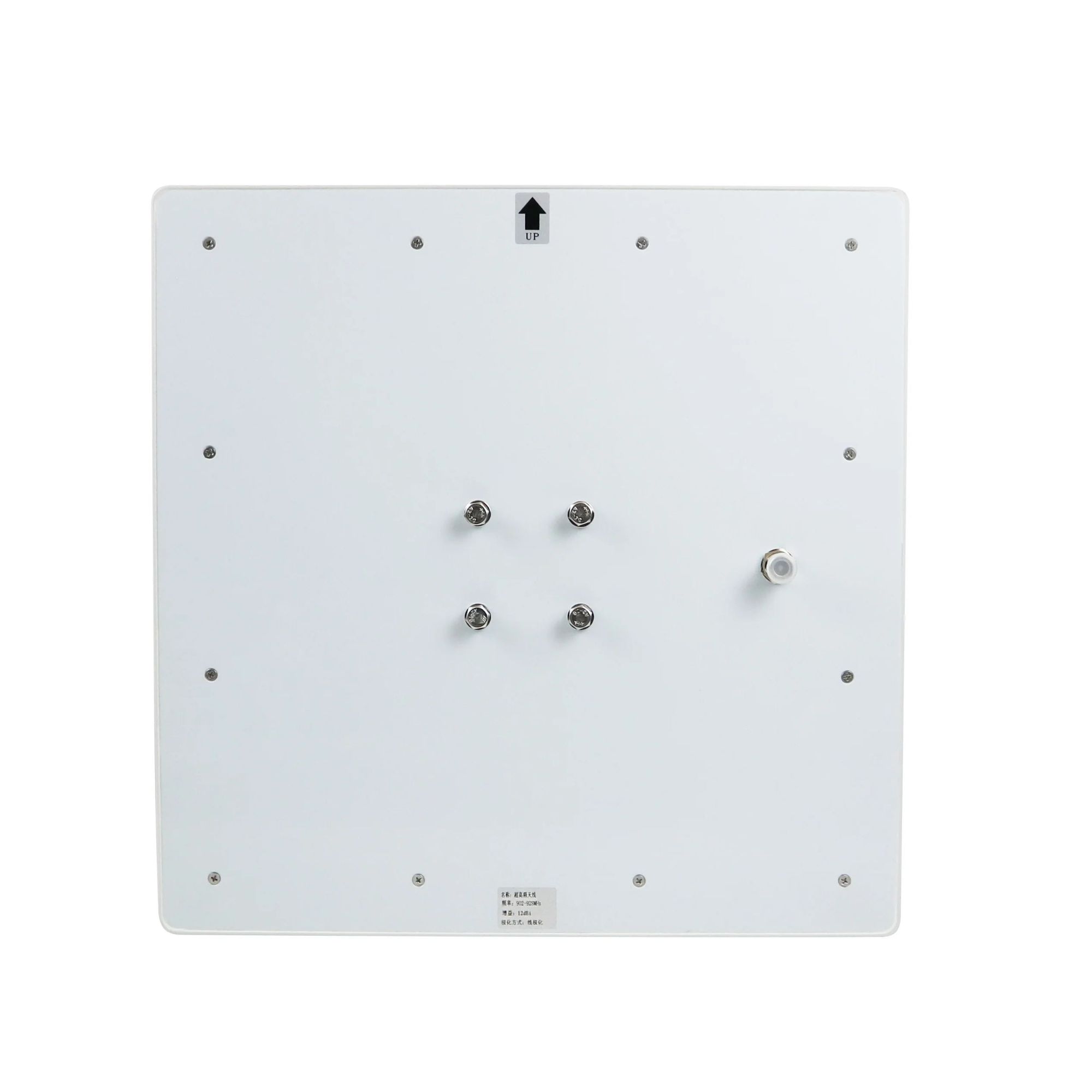
| Polarisation | Linear. Mount with the UP arrow upward and do not rotate the panel. |
| Front-to-back ratio | ≥23 dB |
| VSWR | ≤1.3 |
| Impedance | 50 Ω |
| Maximum input power | 100 W survival rating. A reader typically delivers 1–2 W. |
| Lightning protection | DC grounded to the mounting plate, which drains static from the element to the mast |
| MECHANICAL AND ENVIRONMENTAL | |
| Dimensions | 500 × 500 × 85 mm |
| Connector | Single N-type female, rear face |
| Mounting interface | Four threaded studs on a square pattern at the rear centre, taking a tilt bracket |
| Radome | ABS, white, eight perimeter fixings |
| Reflector | Aluminium |
| Ingress protection | IP65 — dust tight and protected against water jets |
| Rated wind velocity | 30 m/s |
| Operating temperature | −40 to +80 °C |
Installation
Everything below is visible in the rear photograph. Read it before you climb the mast.
Four studs on a square pattern allow four rotations and only one of them is correct. Align the arrow upward, then check the tags at the far edge of the beam rather than directly in front.
A fixed mount rarely points where you need it. A tilt bracket lets you set the down-angle so the footprint lands on the floor at the distance you planned, instead of on the wall opposite.
IP65 is decided at the cable entry, not across the radome. Use a low-loss 50 Ω cable and seal the joint with self-amalgamating tape or a weatherproof boot. Use N-type rather than SMA for an outdoor run; every 3 dB of cable loss halves your effective range.
The element is DC-connected to the mounting plate, so static picked up by the antenna drains to the mast instead of into the reader front end. In a high-lightning area that does not replace a proper mast earth and a surge arrestor on the coax: ground the mast, not just the antenna.
In use
A high-gain narrow-beam antenna is a precision instrument. It is excellent at a defined opening and poor at a general area.
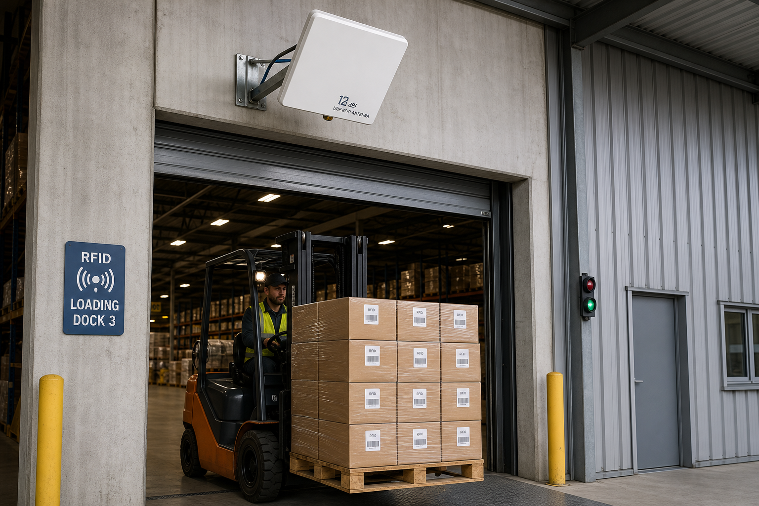
Dock doors and conveyor lanesA defined opening, cartons that are always the same way up, and a reading zone 2 to 4 metres wide. This is the ideal case: the linear polarisation matches the label, the narrow beam keeps the antenna from reading the racking behind it, and the bracket angle sets the footprint exactly.
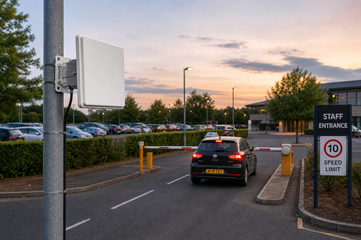
Vehicle lanes and yard gatesA windscreen label has a fixed orientation relative to the lane, so linear works, and the throw length is what buys the 12 dBi. Aim it along the lane rather than across it — the same beam that reaches 15 metres is only a few metres wide once it gets there.
A doorway of people, garments on a rail, loose assets in a bin — the tags arrive at every angle, so half of them are partly cross-polarised and some are invisible. Add a narrow beam and the geometry gets worse: people walk through the edges of the cone where the field is weakest. For those installs you want a circular antenna with a wider beam and less gain.
Questions we are asked
The unit shown is 902–928 MHz, which is the FCC band used in the United States, Canada, Brazil and much of Asia and Latin America. If you are installing in an ETSI market — the EU, the UK, and most of the Middle East and Africa — you need an 865–868 MHz antenna, which is a different tuning. Tell us the country and we will confirm which one your order should be.
A single N-type female connector on the rear face. N-type is the standard for reader antenna runs because it is weatherproof and low-loss at 900 MHz; SMA is smaller but not rated for the same outdoor duty. Use a low-loss 50 ohm cable, because every 3 dB of cable loss costs you half your range — the same as halving the antenna.
Mount with the UP arrow upward so the polarisation plane is vertical, then aim the panel at the middle of the zone you want to cover. The beam is 42 degrees horizontally, so at ten metres it is about 7.7 metres wide. Tilt it down slightly for a floor-level zone, and test the tags at the far edge of the cone rather than at the centre, because the centre will always read.
Because both the antenna and the tags are linearly polarised. A tag lying flat presents its dipole horizontally, which is cross-polarised to a vertically mounted panel and effectively invisible. Either rotate the panel 90 degrees, or specify a circular antenna. More reader power will not solve it.
Only if the reader has two antenna ports, and then it switches between them rather than reading both at once, which halves the time each port gets. For two zones that must be read independently, two reader ports or two readers is the cleaner answer.
It is the maximum the antenna will survive, not what it needs. Readers output one to two watts. The figure tells you the antenna will not be damaged by a high-power reader or a nearby transmitter.
The element is DC-grounded to the mounting plate, which drains static and gives a path for induced surges. That does not replace a proper mast earth or a surge arrestor on the coax in a high-lightning area. Ground the mast, not just the antenna.
Send us the reader model, the tag you are using and a photograph of where the antenna will go. We will confirm the band, tell you what range to expect at that spot, and say whether linear will work or you need circular — before you order.
Copyright © ©Copyright 2024 Greatest IoT Technology Co., Ltd all rights reserved - Privacy policy